CALL 800-985-6929
Mon-Fri 7AM - 7PM CST


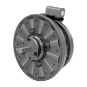


Warner Electric PCB-1525/1225 Heavy Duty
- PCB Series
- Voltage: 6/24/90 VDC
- Static Torque: 465/700 lb. ft.
- Max RPM: 2,000 rpm
- Shaft Size: 937 3.000
The PCB Series clutch-brakes combine a PC clutch and a PB brake into one compact design.
SPECIFICATIONS
| Model Name | PCB-1525/1225 Heavy Duty |
| Function | Primary Clutch Brake |
| Shaft Size | .937 – 3.000 |
| Max. Rated Torque | 700/465 lb. ft. |
| Max. RPM | 2,000 rpm |
| Standard Voltage | 6, 24, 90 DC |
| Outside Diameter | 12.75 inches |
| Overall Length | 7.25 Inches |
| Manufacturer Drawing | I-25636 |
SERIES DESCRIPTION
Custom design brakes and clutches are user-assembled from standard components for optimum performance in the smallest possible package size.
- Easily adaptable to any mounting requirement
- Low initial cost
- Wide range of models and options
CATALOG & MANUALS
| Catalog | Warner Electric Basic Design Clutches Brakes Catalog | |
| Users Manual / Installation Instructions | Warner Electric PCB-1525/1225 Users Manual / Installation Instructions | |
| Quick Information | Warner Electric PCB-1525/1225 HD Quick Information |
HOW TO ORDER
(Please provide the following with your quote request)
1. Specify Voltage for Item 4 and Item 11A or 11B.
2. Specify left hand or right hand hub for Item 5. Bushing enters from magnet side for L.H. hub and from hub side for R.H.
3. Specify Bore Size for Item 7.
4. Specify Inside Mounted for Items 10A and 11A or Outside Mounted for Items 10B and 11B.
5. See Controls Section.
Example:
PCB-1525/1225 Clutch Brake per I-25635 – 90 Volt, Left
Hand hub, 2” Bore, Inside Mounted


| PCB-1525/1225 Heavy Duty Parts List | |||
| Item | Description | Part Number | Qty. |
| 1 | Splined Hub | 540-0148 | 1 |
| 2 | Mounting Accessory | 5202-101-001 | 1 |
| 3 | Armature Assembly | 5324-111-001 | 1 |
| 3-1 | Armature | 5324-111-034 | 1 |
| 3-2 | Splined Armature Adapter | 104-0011 | 1 |
| 3-3 | Autogap Spring | 808-0044 | 1 |
| 3-4 | Retainer Ring | 748-0370 | 1 |
| 3-5 | Retainer Plate | 686-0003 | 1 |
| 3-6 | Buttonhead Screw | 797-0272 | 8 |
| 3-7 | Locknut | 661-0004 | 8 |
| 4 | Mounting Accessory | 5321-101-001 | 1 |
| 5 | Magnet Assembly | ||
| 6 Volt | 5304-631-009 | ||
| 24 Volt | 5304-631-011 | ||
| 90 Volt | 5304-631-010 | ||
| 5-1 | Terminal Accessory | 5311-101-001 | 1 |
| 6 | Hub Assembly | ||
| Left Hand (shown) | 5304-541-001 | ||
| Right Hand | 5304-541-002 | ||
| 7 | Bushing* | 180-0262 to 180-0295 | 1 |
| 8 | Brushholder | 5300-178-001 | 1 |
| 8-1 | Brush | 176-0001 | 4 |
| 9 | Armature Assembly | 5303-111-009 | 1 |
| 10 | Autogap Accessory | 5201-101-008 | 4 |
| 11A | Magnet – Inside Mounted | 1 | |
| 6 Volt | 5313-631-005 | ||
| 24 Volt | 5313-631-006 | ||
| 90 Volt | 5313-631-007 | ||
| 11A-1 | Terminal Accessory | 5311-101-001 | 1 |
| 11B | Magnet – Outside Mounted | 1 | |
| 6 Volt | 5313-631-010 | ||
| 24 Volt | 5313-631-012 | ||
| 90 Volt | 5313-631-011 | ||
| 11B-1 | Terminal Accessory | 5311-101-001 | 1 |
| 12A | Mounting Accessory I.M. | 5321-101-001 | 1 |
| 12B | Mounting Accessory O.M. | 5321-101-002 | 2 |
| 13 | Conduit Box | 5200-101-011 | 1 |