CALL 800-985-6929
Mon-Fri 7AM - 7PM CST


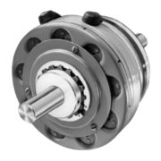


Warner Electric PCC-500 Heavy Duty
- PCC Series
- Voltage: 6/24/90 VDC
- Static Torque: 40 lb.ft.
- Max RPM: 5,400 rpm
- Shaft Size: .750 – 1.250
- Magnet Shaft Size: .500 – 1.250
The PCC Series clutch couplings employ the same basic components as the PC design except for a splined hub and adapter which serves as a coupling for in-line shaft applications.
SPECIFICATIONS
| Model Name | PCC-500 |
| Function | Primary Clutch Coupling |
| Armature Shaft | .500 – 1.250 |
| Magnet Shaft | .500 – 1.250 |
| Static Torque | 40 lb.ft. |
| Max. RPM | 5,400 rpm |
| Standard Voltage | DC 6, 24, 90 |
| Outside Diameter | 6 Inches |
| Overall Length | 4.25 Inches |
| Manufacturer Drawing | I-25543 |
SERIES DESCRIPTION
Custom design brakes and clutches are user-assembled from standard components for optimum performance in the smallest possible package size.
- Easily adaptable to any mounting requirement
- Low initial cost
- Wide range of models and options
CATALOG & MANUALS
| Catalog | Warner Electric Basic Design Clutches Brakes Catalog | |
| Users Manual / Installation Instructions | Warner Electric PCC-500 HD Users Manual / Installation Instructions | |
| Quick Information | Warner Electric PCC-500 HD Normal Duty Quick Info |
HOW TO ORDER
(Please provide the following with your quote request)
1. Specify Bore Size for Item 1 and Item 5.
2. Specify Voltage for Item 6.
3. See Controls Section.
Example:
PCC-500 Clutch Coupling per I-25543 – 90 Volt, 3/4” Armature Hub Bore, 1” Bushing Bore

3. See Controls Section

| PCC-500 Heavy Duty Parts List | |||
| Item | Description | Part Number | Qty. |
| 1 | Armature Hub | 1 | |
| 3/4″ Bore | 5200-541-002 | ||
| 7/8″ Bore | 5200-541-003 | ||
| 15/16″ Bore | 5200-541-004 | ||
| 1″ Bore | 5200-541-005 | ||
| 1-1/8″ Bore | 5200-541-006 | ||
| 1-1/4″ Bore | 5200-541-007 | ||
| 2 | Armature Assembly | 5230-111-002 | 1 |
| 2-1 | Armature | 5230-111-001 | 1 |
| 2-2 | Retainer Ring | 748-0355 | 1 |
| 2-3 | Autogap Spring | 808-0412 | 1 |
| 2-4 | Retainer Plate | 748-0364 | 1 |
| 2-5 | Screw | 797-0028 | 3 |
| 3 | Magnet Hub | 5300-541-001 | 1 |
| 3-1 | Collector Ring | 5300-749-001 | 1 |
| 3-2 | Collector Ring Mounting Acc. | 5300-101-002 | 1 |
| 4 | Brushholder | 5300-178-001 | 1 |
| 4-1 | Brush | 176-0001 | 4 |
| 5 | Bushing* | 2 | |
| 1/2″ to 1-1/4″ Bore | 180-0116 to 180-0128 | ||
| 6 | Magnet | 1 | |
| 6 Volt | 5300-631-002 | ||
| 24 Volt | 5300-631-003 | ||
| 90 Volt | 5300-631-005 | ||
| 6-1 | Terminal Accessory | 5311-101-001 | 1 |
| 7 | Mounting Accessory | 5102-101-001 | 2 |