CALL 800-985-6929
Mon-Fri 7AM - 7PM CST


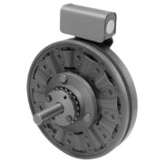


Warner Electric SFC-825 Flange Mounted
The SFC Series clutch couplings employ the same basic components as the SF design except for a splined hub and adapter which serves as a coupling for in-line shaft applications.
SPECIFICATIONS
| Model Name | SFC-825 Flange Mounted |
| Function | Stationary Field Clutch Coupling |
| Armature Shaft | .500 – 1.500 |
| Rotor Shaft | .500 – 1.250 |
| Static Torque | 125 lb.ft. |
| Max. RPM | 4,000 rpm |
| Standard Voltage | DC 6,24, 90 |
| Outside Diameter | 8.75 Inches |
| Overall Length | 4.5 Inches |
| Manufacturer Drawing | I-25564 |
SERIES DESCRIPTION
Custom design brakes and clutches are user-assembled from standard components for optimum performance in the smallest possible package size.
- Easily adaptable to any mounting requirement
- Low initial cost
- Wide range of models and options
CATALOG & MANUALS
| Catalog | Warner Electric Basic Design Clutches Brakes Catalog | |
| Users Manual / Installation Instructions | Warner Electric SFC-825-FM Users Manual / Installation Instructions | |
| Quick Information | Warner Electric SFC-825-FM- Quick Info |
HOW TO ORDER
(Please provide the following with your quote request)
1. Specify Bore Size for Item 1.
2. Specify Bore Size for Item 7.
3. Specify Voltage for Item 9A or 9B.
4. Specify Inside Mounted for Items 9A and 10A or Outside Mounted for Items 9B and 10B.
5. See Controls Section.
Example:
SFC-825 Clutch Coupling per I-25564 – 90 Volt, Inside Mounted, 1” Bore (Item 1), 1” Bore (Item 7)


| SFC-825 Flange Mounted Parts List | |||
| Item | Description | Part Number | Qty. |
| 1 | Bushing* | 1 | |
| 1/2″ to 1-1/2″ Bore | 180-0002 to 180-0018 | ||
| 2 | Retainer Ring | 748-0006 | 1 |
| 3 | Splined Hub | 540-0057 | 1 |
| 4 | Armature & Splined Adapter | 5201-111-001 | 1 |
| 4-1 | Capscrew | 797-0341 | 3 |
| 4-2 | Splined Adapter | 104-0008 | 1 |
| 4-3 | Autogap Accessory | 5321-101-006 | 1 |
| 4-4 | Spacer | 748-0333 | 3 |
| 4-5 | Armature | 5321-111-022 | 1 |
| 4-6 | Locknut | 661-0004 | 3 |
| 5 | Mounting Accessory | 5201-101-007 | 1 |
| 6 | Rotor | 1 | |
| Standard Friction Material | 5201-751-003 | ||
| Optional LK Facing | 5201-751-007 | ||
| 7 | Bushing* | 1 | |
| 1/2″ to 1-1/4″ Bore | 180-0101 to 180-0013 | ||
| 8 | Rotor Hub | 540-0013 | 1 |
| 9A | Field – Inside Mounted | 1 | |
| 6 Volt | 5201-451-006 | ||
| 24 Volt | 5201-451-008 | ||
| 90 Volt | 5201-451-010 | ||
| 9B | Field – Outside Mounted | 1 | |
| 6 Volt | 5201-451-014 | ||
| 24 Volt | 5201-451-016 | ||
| 90 Volt | 5201-451-018 | ||
| 10A | Mounting Accessory – I.M. | 5321-101-001 | 1 |
| 10B | Mounting Accessory – O.M. | 5321-101-002 | 1 |
| 11 | Conduit Box | 5200-101-012 | 1 |